Capacitor: two conducting plates charged with equal amount of charge of opposite signs, with insulator in between (we assume a vacuum unless said otherwise)
Three quantities characterize a capacitor: 1) surface charge density 2) capacitance 3) dielectric constant
Capacitance (q= C x ∆V) Unit: Farad (F)
The potential difference across a parallel plate capacitor is proportional to the charge on the plates. The proportionality factor is called capacitance
Capacitance is the ability of a body to hold an electrical charge. Capacitance is also a measure of the amount of electrical energy stored (or separated) for a given electric potential. A common form of energy storage device is a parallel-plate capacitor. In a parallel plate capacitor, capacitance is directly proportional to the surface area of the conductor plates and inversely proportional to the separation distance between the plates. The ratio of charge on each plate to the potential difference arose the capacitor!
Large capacitance Small: potential difference
C= (e0 xA)/ b
The capacitance of parallel plate capacitor depends only on geometric properties; it is proportional to the area of the plates and inversely proportional to the width of the gap between the plates.
Dielectric constant (k)= material constant (NO UNITS) [k x e0] represents the permittivity of the dielectric!
C= (e0 xA)xk/ b ß correction factor when outside of a vacuum as the insulator
Q= C x ∆V
Case 1: fixed charge (you disconnect the battery) so if capacitance increases potential different (voltage) decreases and vice versa
Case 2: flexible charge (still connected to battery and potential difference remains constant) so if you increase capacitance, you also increase charge to keep potential constant
***Charge capacitors store electric potential energy!
When you first transfer charge, ∆q, from one plate to the other, NO WORK IS DONE because the capacitor still has 0 potential difference. However as you continue to transfer the same amount of charge step by step, work is required!
Moving charges against the electrical force W= ∆q x ∆V
Overall process: W= (1/2)xQx∆Vfinal
Electrical Current (Amperes= C/s)
An electric current is defined as the amount of charge transferred through a cross-sectional area of a conductor per time unit
I= ∆q/ ∆t= n x e x vd x A
A force is required to move an electron along a wire (which is equal to F=ma, leading to small electron speed) **electrons move in a direction opposite to the current.
Drift Velocity: the motion of point charges is indicated
Current is proportional to: density of mobile point charges, drift velocity, geometric cross-sectional area of wire.
Due to its dependency on the cross-sectional area (A) the current I is not a parameter characteristic for the conductor material (NOT A MATERIAL CONSTANT)
Current density (a/m^2): J= I/A= n x e x vd
Resistance
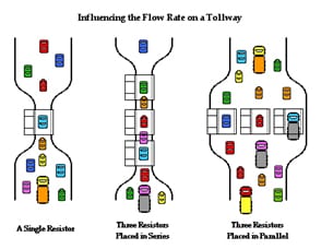
Resistance against the flow of point charges through a conductor (relates potential difference to current) potential difference along a given conductor vs. current it carries! Increases with length, decreases with increase in A, cross-sectional area.
R= V/I = (p x l)/A (units: V/A=Ω)
Resistivity: proportionality factor between the magnitude of the electric field, which causes point charges to move, and current density which represents the charge flow rate. (Material dependent)
|E|= p x J (p=resistivity) (units: V x m/A)
Materials behave Ohmically: electrical field if proportional to current density
Superconductors: no resistivity at low temperatures
Conductivity (ϒ)
Conductivity is defined as the inverse value of the resistivity: ( ϒ= 1/p) units: 1/(Ωxm)
**Used the describe movement through a resistors than hindrance of motion of point charges.


